
Using BIM on Construction Projects
Building Information Modeling is one of the most transformative innovations to hit the construction industry in the last 100 years. With the ability to build systems and entire buildings virtually before they are permitted and mobilized in the field, it is possible to drive the risk and uncertainty down significantly on projects.Once a system is designed and coordinated in a model, it can be prefabricated and installed with higher productivity and more safely than traditional methods.
Innovation is also taking place in the close out and turn over process at the completion of projects with potential for major advances in building management over the entire life cycle.
WHY: Potential outcomes of successful BIM implementation on capital projects.
- Reduce Change Orders
- Safer Projects
- Faster Project Schedules
- Increased Quality
- Lower Overall Project Cost
- Comprehensive As-Builts and Turn Over Documentation
- Efficient Buildings for Operations and Facility Management


HOW: Uses of Building Information Modeling
- Creating Buildable and Coordinated Set of Plans
- Automated and Accurate Layout
- Inserting of Hangers Before Deck Pours
- Prefabrication of MEP and Walls
- Facilitation of Takt Time Planning
- Earlier and Comprehensive Stake Holder Engagement
- Create Buy In Among Different Trades
- Resolve Issues Earlier
WHAT: Practical Implementation Tools and Concepts
- Clash Detection
- Laser Scanning
- Total Station
- Design for Fabrication
- Energy Modeling
- Virtual Reality Walk-Throughs
- Collaborative Model Reviews
- Take the Model to the Field
- Embedded Data within Turn Over Package

Coordination During Design

Clash Detection:
One of the most important innovations in modeling of building systems is the ability to identify where two systems occupy the same physical space in a model. This is known as a clash.
With a viewer, teams are able to view multiple models in the same space (architectural, plumbing, mechanical, framing, etc) and look for clashes.
The team can then rearrange the design so that none of the systems conflict. By doing this prior to fabrication and installation, many traditional RFIs and change orders are avoided. This also leads to higher productivity for installation with less down down, less rework and less wasted material.
Coordinated MEP, Framing and Structural Design:
Once the team resolves all of the clashes, the model is a can now be built without rework and conflict in the field. The next step is to make sure that the work is actually installed per the model. This is easier said than done.
Incorporating As-Built / Existing Conditions
Laser Scanning:
In an existing building, if there is an opportunity to demolish the existing improvements before you complete the design for the new space or if the space is open, laser scanning can be a valuable tool.
A laser scanner will shoot out a laser beam and measure the amount of time it takes to reflect back off the surface. It will place a point where it bounced off the surface.


Point Cloud:
Thousands of these points make up a point cloud. The image at the right is an example of a point cloud. The point cloud contains three dimensional information for each point. With a proper viewer, it is possible to manipulate the point cloud and take measurements between points.
Modeling of Existing Conditions:
It is possible to use a point cloud to make a 3 dimensional model of the existing conditions. With this 3 dimensional as-built as a background, the new space can be designed within the existing conditions without clashes.
If it is not possible to demo the space prior to commencing with design, a point cloud can be taken prior to demolition. The work of creating the as-built model is significantly more work as someone will need to go into the point cloud and identify which systems need to be modeled and which systems do not need to be modeled. Many of the systems will be demolished before construction of the new space starts, so they should not be included in the as-built model.


Identifying Existing Conditions for Modeling:
Here is an example of existing conditions with field notes to the modeler of what each system is (ie waste, domestic water, emergency power, etc) and whether it should be included in the new model or left out.
Using the Model for Fabrication
Prefabricating Systems:
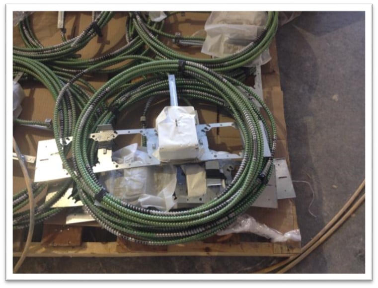 With a coordinated, buildable model, many systems can now be prefabricated in a manufacturing setting. Many companies use the model files to drive automated machines to make ductwork, cut pipes, and create spool drawings for common racks and electrical fitting.
These pieces are made in a shop and can be pre-assembled into larger pieces, only limited by what can fit on a truck and how it can be loaded into a building and moved to the final place of installation.
The industry is moving away from a craft based method of creating work in the field to a supply chain focus with parts delivered in the sequence they are needed for install and assembled on site from pre packaged kits of parts.

Automating Layout from the Model

Total Station Layout:
With a coordinated model, it is possible to create a two dimensional plan of all of the attachment points of each system.
This plan will show the dimensions of every anchor based on where it connects with structure and the x, y coordinates from grid lines.
Loading this plan into a Total Station allows a team of two people to identify locations of hangers more accurately and significantly faster than with traditional layout methods.
Inserting Hangers and Anchors Prior to Concrete Pours:
On new builds with concrete decks, it is possible (and becoming standard in some areas), to insert the hangers for the future build out prior to pouring the concrete deck.
The hanger locations are laid out on the deck (usually on top of the deck for the systems to be installed on the floor below). A crew punches the hangers and anchors down through the metal deck.
The photo shows the deck below with the plumbing and mechanical hangers installed prior to placement of concrete. This allows the hangers to go in quickly and eliminates most overhead drilling, a cause of many eye injuries.
Due to the accuracy of the model, the hangers themselves can also be prefabricated and cut to length in the shop. Once the concrete sets, these hangers are screwed into the anchor that was placed through the deck above and do not need to be cut in the field, further saving time and increasing quality.


Using the Model for Scheduling


3D to 4D - Incorporating Schedule into the Model:
Clash detection helps with making coordinated models. It is possible to model systems which fit in a final condition but the sequence of installing the components is actually difficult or impossible. Incorporating schedule into the model can allow the team to visualize the installation sequence of the work and look for issues (schedule clashes vs physical clashes).
This example shows generators being removed from an electrical room, the clear space once they are removed and the new electrical distribution system installed in the clear space. It is possible to look at schedule by using layers within the model and software is available to tie a scheduling software to a model and create an animation of the install sequence.